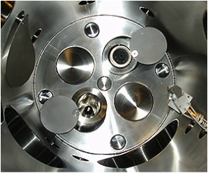
Thermal Evaporation is one of the simplest of the Physical Vapor Deposition (PVD) techniques. Basically, material is heated in a vacuum chamber until its surface atoms have sufficient energy to leave the surface. At this point they will traverse the vacuum chamber, at thermal energy (less than 1 eV), and coat a substrate positioned above the evaporating material (average working distances are 200 mm to 1 meter).
The pressure in the chamber must be below the point where the mean free path is longer than the distance between evaporation source and the substrate. The mean free path is the average distance an atom or molecule can travel in a vacuum chamber before it collides with another particle thereby disturbing its direction to some degree. This is typically 3.0 x 10⁻⁴ Torr or lower. The main reason to run at the high end of the pressure range is to allow an ion beam source to be employed simultaneously for film densification or other property modification.
As a result of its simplicity, the cost of equipment ownership is also somewhat lower.
THERMAL EVAPORATION SOURCES
Resistive Boat or Coil.
|
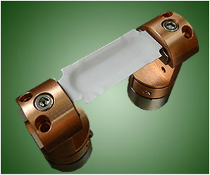
A pair of high current vacuum feedthroughs are employed to flow a significant current (e.g. 300A) through a wide ribbon of refractory metal (e.g. tungsten, molybdenum) that has been pressed to have a large "dimple" on the top side into which pellets of the material are placed. As the current is increased, this thermal "boat" gets hotter and hotter until the pellets of material melt and eventually evaporate. As the evaporation process consumes energy, it is necessary to keep the current flowing to keep the evaporation process going. Increasing the current will increase the rate of evaporation and vice versa. It is also possible to utilize a coil made of a similar refractory metal. Source material is generally shaped into small horseshoe shapes and draped over the coil. As the source material heats and melts it "wets" the surface of the coil and subsequently evaporates in all directions. As a result, it directs its material less efficiently than the "boat" which only evaporates "up". |
Knudsen Cell ("K" Cell), RadakTM Furnace and Custom Made Sources
|
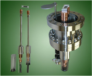
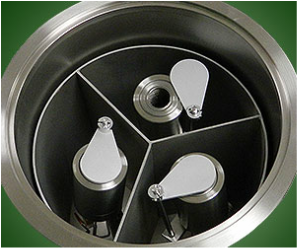
Knudsen cells, Radak furnaces and other custom made thermal sources generally utilize a containment crucible which is surrounded or exposed to a controllable heat source such as a tungsten or tantalum resistance wire (coiled around the crucible), a resistive element or puck or even a quartz lamp. The crucible is heated in a controlled fashion utilizing a thermocouple sensor and a closed PID heater controller. The source material is thereby heated, melted and evaporates from the open end of the crucible and rate is increased or decreased with power input (~heating element temperature). |

| 카테고리 | 제목 | 작성자 | 조회수 | |
|---|---|---|---|---|
| E-BEAM EVAPORATION | TUTORIALS FOR ELECTRON BEAM (E-BEAM) EVAPORATION file | YEONJIN | 3252 | TUTORIALS FOR ELECTRON BEAM (E-BEAM) EVAPORATION file |
| THERMAL EVAPORATION | TUTORIALS FOR THERMAL EVAPORATION file | YEONJIN | 2750 | TUTORIALS FOR THERMAL EVAPORATION file |
| SPUTTERING | WHAT IS SPUTTERING? file | YEONJIN | 3028 | WHAT IS SPUTTERING? file |
| ION MILLING | WHAT IS ION MILLING? file | YEONJIN | 3107 | WHAT IS ION MILLING? file |
| 재료시험기 | FINAT Standards | 관리자 | 1912 | FINAT Standards |
| 재료시험기 | PSTC Standards | 관리자 | 2071 | PSTC Standards |
| 재료시험기 | EN Standards | 관리자 | 1602 | EN Standards |
| 재료시험기 | ISO Standards | 관리자 | 2415 | ISO Standards |
| 재료시험기 | ASTM Standards file | 관리자 | 4657 | ASTM Standards file |
| 열전도도측정기 | Fundamentals of measuring λ | 관리자 | 1606 | Fundamentals of measuring λ |
| 열전도도측정기 | 유체의 열전도도 | 관리자 | 1627 | 유체의 열전도도 |
| 점도계 | The QVis Quartz sensor | 관리자 | 1256 | The QVis Quartz sensor |