INSTEC은 1984년부터 정밀한 온도컨트롤 스테이지와 관련 기기를 구축해 왔습니다. 첫 스테이지는 액정 응용 분야를 위해 설계되었지만 INSTEC은 모든 산업 분야의 연구 개발 요구에 맞춰 최신 현미경 및 분광기의 모든 기술에 맞는 업그레이드된 thermal stage를 제공하고 있습니다. Dual top-bottom heating, 샘플 높이에 따른 가변 챔버, 넓은 시야각 및 편리한 샘플 처리와 같은 고유한 기능으로 heating, cooling stage를 생산합니다. INSTEC은 마켓에서 최고 품질의 완성품을 제공하고자 업계 최고의 재료와 부품을 사용하고 있습니다. 또한 어떠한 애플리케이션에도 맞는 적절한 커스터마이즈가 가능합니다.

STAGE SELECTION GUIDE
THERMOELECTRIC STAGES |
||||
|
MODEL |
TEMPERATURE CONTROL |
SAMPLE AREA |
CHAMBER ATMOSPHERE CONTROL |
FEATURES & APPLICATIONS |
|
-25°C - 90°C |
Φ 40.5 mm |
Gas tight chamber |
Inverted microscopy |
|
|
-25°C - 120°C |
45 mm x 45 mm |
No chamber |
Standard microscope slides |
|
|
-25°C - 90°C |
Φ35 mm or 25 mm x 75 mm |
Gas tight sample chamber |
Inverted microscopy |
|
|
-40°C - 120°C |
38 mm x 52 mm |
Side loading chamber |
Standard microscope slides |
|
|
-40°C - 120°C |
42 mm x 42 mm |
Gas / Vacuum tight chamber |
Standard microscope slides |
|
|
-40°C - 180°C |
12.5 mm x 12.5 mm |
Flip lid and dark chamber |
Spectrophotometry with standard cuvettes |
|
HEATING & COOLING STAGES |
||||
| MODEL | TEMPERATURE CONTROL | SAMPLE AREA | CHAMBER ATMOSPHERE CONTROL | FEATURES & APPLICATIONS |
|
-60°C - 400°C |
38 mm x 50 mm |
Side loading chamber |
Standard microscope slides |
|
|
-60°C - 400°C |
38 mm x 50 mm |
Side loading chamber |
Dual top & bottom heating |
|
|
-60°C - 600°C |
12.5 mm x 12.5 mm |
Flip lid and dark chamber |
Spectrophotometry with standard cuvettes |
|
|
-190°C - 100°C |
28 mm x 30 mm |
Gas tight chamber |
Spectroscopy: FTIR, Raman, X-ray |
|
|
-190°C - 100°C |
28 mm x 30 mm |
Vacuum tight chamber |
Spectroscopy: FTIR, Raman, X-ray |
|
|
-190°C - 250°C |
23 mm x 28 mm |
Gas tight chamber |
Inverted microscopy |
|
|
-190°C - 400°C |
38 mm x 50 mm |
Gas tight chamber |
Spectroscopy: FTIR, Raman, X-ray |
|
|
-190°C - 400°C |
28 mm x 30 mm |
Vacuum tightchamber |
Spectroscopy: FTIR, Raman, X-ray |
|
|
-190°C - 600°C |
28 mm x 30 mm |
Gas tight chamber |
Spectroscopy: FTIR, Raman, X-ray |
|
|
-190°C - 600°C |
24 mm x 24 mm |
Gas tight chamber |
Spectroscopy: FTIR, Raman, X-ray |
|
|
-190°C - 600°C |
24 mm x 24 mm |
Gas tight chamber |
Spectroscopy: FTIR, Raman, X-ray |
|
HIGH TEMPERATURE HEATING STAGES |
||||
| MODEL | TEMPERATURE CONTROL | SAMPLE AREA | CHAMBER ATMOSPHERE CONTROL | FEATURES & APPLICATION |
|
30°C - 1000°C |
16 mm x 16 mm |
Gas tight chamber |
IR microscopy & spectrocopy |
|
|
30°C - 1200°C |
Φ 8 mm |
Gas tight chamber |
ceramics, metallurgy, geology |
|
|
30°C - 1300°C |
Φ 8 mm |
Gas tight chamber |
IR microscopy & spectrocopy |
|
|
30°C - 1400°C |
16 mm x 16 mm |
Gas tight chamber |
ceramics, metallurgy, geology |
|
|
30°C - 1500°C |
Φ 8 mm |
Gas tight chamber |
ceramics, metallurgy, geology |
|
SPECIALTY STAGES |
||||
|
MODEL |
TEMPERATURE CONTROL |
SAMPLE AREA |
CHAMBER ATMOSPHERE CONTROL |
FEATURES & APPLICATIONS |
|
-190°C - 120°C |
3 mm x 3 mm grids |
Side loading chamber |
Cryogenic, upright microscopy |
|
|
-190°C - 120°C |
3 mm x 3 mm grids |
Side loading chamber |
Cryogenic, Inverted microscopy |
|
|
-190°C - 350°C |
26 mm x 16 mm |
Gas tight chamber |
Tensile strength measurement |
|
|
-190°C - 600°C |
28 mm x 30 mm |
Gas tight chamber |
geology: fluid inclusions |
|
MINI ELECTRICAL PROBE STAGES |
||||
|
MODEL |
TEMPERATURE CONTROL |
SAMPLE AREA |
CHAMBER ATMOSPHERE CONTROL |
FEATURES & APPLICATIONS |
|
-30°C - 180°C |
40 mm x 40 mm |
Gas tightchamber |
4 electrical probes |
|
|
-190°C - 400°C |
28 mm x 30mm |
Vacuum tight chamber |
4 electrical probes |
|
|
-190°C - 600°C |
28 mm x 30 mm |
Gas tight chamber |
4 electrical probes |
|
|
-190°C - 600°C |
28 mm x 30 mm |
Gas tight chamber |
4 electrical probes, Non-magnetic (Hall effect measurements) |
|
|
RT - 1000°C |
16 mm x 16 mm |
Gas tight chamber |
4 electrical probes |
|
STAGE FEATURES
THERMAL BLOCK
- The heart of all electrical probe systems, stages, chucks, and thermal plates is a thermal block or sample plate for heating and cooling
- Built from aluminum, silver, or ceramic depending on the intended temperature range
- Embedded with heating elements and liquid nitrogen cooling channels as well as temperature sensors to provide the most precise thermal control for the sample
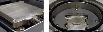
SAMPLING AREA
- The sample area of the heating block is the effective area over which the set temperature is maintained
- Typically flat to heat and cool samples from the bottom, but can be designed to accommodate samples of different dimensions
- Sample surfaces can be made with/without a transmission aperture
- Chuck surfaces can be made with vacuum grooves for securely fixing samples
- Place samples directly on the surface, on or in the arm of the XY positioning mechanism, or in custom-built holders
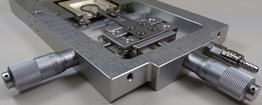
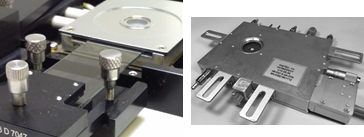
SAMPLE POSITIONING
- Position samples anywhere within the sampling area for fast in situ adjustments
- Precisely align specific sample features in optical paths
- Consists of a thin metal square or circular looped arm that extends over part of the sample area
- Arm is controlled externally by Vernier dials with 10mm of travel in two dimensions
- Greater flexibility, sample area accessibility, and precision control in moving the sample inside the chamber than in moving the stage on the microscope
- XY positioning is optimal for use with a rotational stage on a polarizing microscope due to the directional nature of polarization
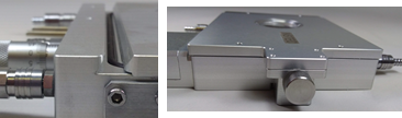
FRAME & OUTER COVER
- Solid lightweight aluminum construction for some models
- Cover edge slides easily under beveled lip in the frame and cover is held securely in place with spring-loaded screws, for some models
CHAMBER HEIGHT & INNER COVER
- The chamber height is the distance between the top surface of the thermal block and the bottom surface of the outer cover, when inner cover is present
- This distance is minimized in design to allow for just enough height for intended samples (slides, slipcovers, wafer pieces, and any clamps or probes) and to decrease the minimum objective working distance
- Some stages feature a removable inner cover with a separate built-in window
- The inner cover significantly reduces vertical temperature gradients
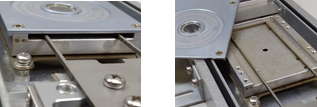
SAMPLE LOADING
- Some models feature convenient sample side loading and unloading without opening stage covers
- Some models feature covers configurable to swing or pivot from any single corner for quick sample access
MOUNTING
- Various mounting adaptors are available for all most all microscope models, or other instruments
- Vertical mounting is possible for almost all Instec stages, for horizontal beam access to the samples
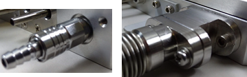
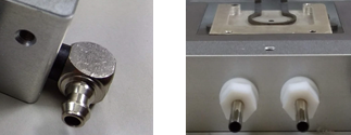
GAS PURGING & VACUUM PORTS
- Some models feature gas purging capability
- Either port can be input or output for purging gas flow
- Some models feature vacuum capability
- Two ports allow one to be used for pumping and the other for a pressure gauge
FRAME COOLING
- For some models, the integrated frame cooling dissipates heat and allows the frame to remain cool or warm to the touch
LIQUID NITROGEN COOLING
- Integrated liquid nitrogen cooling on some models allows precision thermal control down to -190C
- Different LN2 pump options are available
- Different Dewar sizes are available
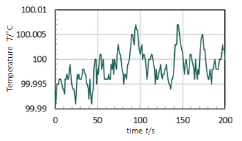
THERMAL CONTROL, mk2000 Temperature Controller
STATIC OPERATION
- In normal operation the controller uses a PID algorithm to adjust heating power and cooling pumping flow to maintain the current temperature
RAMP OPERATION
- To ramp to a user-defined target temperature TT at a specified ramp rate R from a current temperature TC, the controller calculates a target temperature profile
- The controller then adjusts the heating power and cooling pumping flow to achieve the target temperature profile
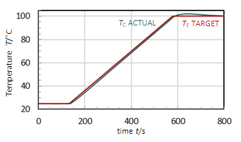
- In a real system, the wiring, a sample on the heating block, and the surrounding atmosphere are thermal loads that dissipate power
- Electrical and thermal inertia can result in short time delays in electrical and thermal responses and in achieving stability in the target temperature
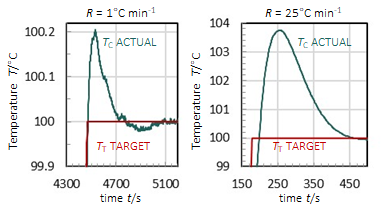
- Faster ramp rates can result in greater overshooting of target temperatures because of thermal inertia
- Overshoot and delay can never be eliminated fully in a real system, but can be minimized by using the slowest ramp rate possible for the process
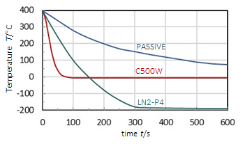
SAMPLE COOLING
- To achieve below ambient temperatures an active cooling system is necessary: a recirculating water chiller or a liquid nitrogen cooling system
- Active cooling has the advantage over passive cooling to allow fast experiment cycling
FRAME COOLING SYSTEMS
- Frame cooling option with recirculating chiller allows thermal control of frame independent of sample thermal block
- Keeps frame safe to touch and prevents frost buildup on windows
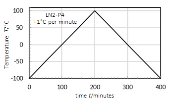
LIQUID NITROGEN COOLING SYSTEMS
- Liquid nitrogen systems provide sample cooling to as low as -190°C depending on pump power and thermal block size
- Systems consist of a pump, a Dewar, a lid with a stoppered port for refilling during operation, and connecting tubing
- Three liquid nitrogen pump output options available, LN2-P2, LN2-P4, and LN2-P8, which suction liquid nitrogen through the equipment and are controlled by the mK2000
- Three Dewar sizes, 2 L, 10 L, and 30 L, with easy refillable lid options to control liquid nitrogen supply to instruments
- Integrates with mK2000 PID controller with ±0.1% resolution
LIQUID NITROGEN SYSTEM MINIMUM TEMPERATURES |
|||
|
LN2-P2
|
LN2-P4
|
LN2-P8
|
|
|
STAGES
|
|||
|
-100°C
|
-190°C
|
-190°C
|
|
-60°C
|
-70°C
|
-80°C
|
|
-160°C
|
-190°C
|
-190°C
|
|
-100°C
|
-190°C
|
-190°C
|
|
NA
|
-60°C
|
-190°C
|
|
NA
|
-190°C
|
-190°C
|
|
CHUCKS & PLATES
|
|||
|
-40°C
|
-60°C
|
-120°C
|
|
-20°C
|
-40°C
|
-100°C
|
|
NA
|
-30°C
|
-80°C
|
|
NA
|
-20°C
|
-60°C
|
|
-120°C
|
-170°C
|
-190°C
|
OPTICAL FEATURES
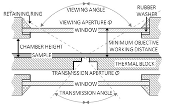
TOP & BOTTOM WINDOWS
- All stages feature a top aperture and many stages feature a transmission aperture and a bottom window
- The top viewing window consists of an opening in the top cover and the bottom window consists of an opening in the bottom frame
- Top and bottom windows are secured with a flat rubber O-ring on the interior side and a metal screwing retaining ring on the exterior side
- The top and bottom aperture magnitude is the effective diameter of the window, limited on the outer edge by the retaining ring and the rubber O-ring
- This aperture magnitude is typically 4 mm less than the window disc diameter
- Different window sizes are available as options.
- Removable and interchangeable windows accommodate the full spectrum of light sources and techniques
- Heat loss scales with window area. Windows are circular and sized according to application to balance maximum viewing angle and minimum heat loss
OPTICAL PATH
- The optical path on stages is through a top viewing window, a transmission aperture in the block, and a bottom window
- The top viewing angle is the maximum angle made from the edges of the window retaining ring and the center of the thermal block top surface
- The top viewing angle depends on the chamber height and the window diameter
- The top viewing angle is double the angle from normal
- The transmission aperture is the minimum diameter of the cylindrical hole through the heating block
- Standard transmission aperture is 2 mm diameter with options of 5 mm or 8 mm diameters
- The transmission angle is the maximum angle made from the edges of the transmission aperture and the center of the thermal block bottom surface
OBJECTIVE & CONDENSER
- The minimum objective working distance is the distance between the top surface of the thermal block and the outer surface of the viewing window
- Sample height reduces the minimum objective working distance
- If the actual objective working distance is less than the minimum working distance, a focused image is not achieved
- Removing the outer windows results in shorter working distances, but compromises sample thermal isolation and risks exposing the lenses to damaging heat
- The minimum condenser working distance is the distance between the bottom surface of the thermal block and the outer surface of the bottom window
- Longer working distance condensers are necessary to focus images through the thermal block using Kohler illumination in modern microscopes
INTEGRATED WINDOW DEFROST
- Some models feature top viewing window defrost mechanism for use with inert or dry gas supply
- One option is an integrated channel in the top cover with a hose port
- Another option is an externally mounted hose holder that allows easy positioning of the hose tip anywhere on the window