Ion Viscosity and Loss Factor
Dielectric permittivity ε* is a quantity with real and imaginary parts:
Conductivity ( σ ) is the sum of frequency independent ( σ DC ) and frequency dependent ( σ AC ) components, as expressed below:
The real part of relative permittivity or relative dielectric constant ( ε ’) also has frequency independent and frequency dependent components, but they will not be treated in this chapter. The real part of relative permittivity or relative dielectric constant ( ε ’) also has frequency independent and frequency dependent components, but they will not be treated in this chapter. In an oscillating electric field, σ DC arises from the flow of mobile ions while σ AC arises from the rotation of stationary dipoles. The dimensionless term loss factor ( ε ”) is a measure of the dissipation, or loss, of electromagnetic energy as heat and is given by:
During the early part of cure, when a thermoset is most conductive, σ DC tends to dominate the dielectric response across a broad range of frequencies. At sufficiently low frequencies σ DC may also be the significant component through the entire cure. When σ DC dominates cure behavior, σ AC is insignificant and loss factor may be approximated as:
In this case, loss factor is inversely proportional to frequency. For example, if the excitation frequency ( ω ) decreases by a factor of 10, loss factor increases by the same factor of 10—this relationship identifies when σ DC dominates the dielectric response and can indicate cure state. During the latter part of cure, frequency dependent conductivity due to dipoles may dominate the dielectric response, especially at higher frequencies. It is important to identify these times and frequencies to avoid misinterpreting data when studying cure.
Cure monitoring with multiple frequencies

Multiple frequency data from cure of five-minute epoxy
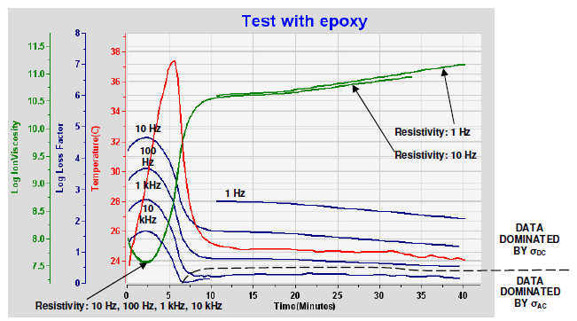
Figure 8-1 shows dielectric data at multiple frequencies during the cure of “five-minute epoxy.” A plot of loss factor can reveal when frequency independent conductivity σ DC dominates the dielectric response. In the early part of this cure, loss factors for 10 Hz, 100 Hz, 1 kHz, and 10 kHz all are inversely proportional to frequency.
In the latter part, however, only loss factors for 1 Hz, 10 Hz and 100 Hz are inversely proportional to frequency. Resistivity ρ is the inverse of conductivity, as expressed in equation 8-5:
When frequency independent conductivity σ DC dominates the data, resistivity is also largely frequency independent. Frequency independent resistivity ρ DC is called ion viscosity , and is characterized by the overlap of curves at multiple frequencies, as shown in Figure 8-1.
During thermoset cure, the change in ion viscosity is typically proportional to the change in mechanical viscosity until they diverge around the time of gelation (See Figure 7-4). Even after mechanical viscosity becomes immeasurable, however, crosslinking continues and the growing polymer network still presents greater and greater resistance to the flow of ions. Consequently, frequency independent resistivity ρ DC —ion viscosity—can be used for determining cure state through the entire cure.
Reference :
Lambient TechnologiesTM Application Note 3.08—Ion Viscosity and Loss Factor, All Page
상세한 사항은 아래 첨부된 자료를 참고 부탁 드립니다.
검색 결과 15건
- 분류 : 유전율측정기


