Information on the angular flux distribution, resulting flow rate distribution, material composition on the substrate, and material efficiency: optimization of the system design.
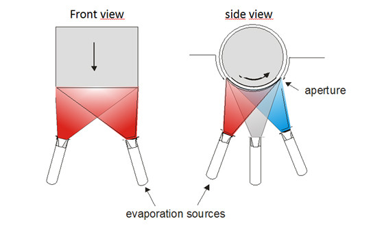
Schematic illustration of the deposition process with 3 pairs of point sources depositing materials onto a moving roll.
-
Why MC-Simulation?
It provides important information while saving time and money -
MC-Simulation allows the optimization of
- source design
- source arrangement
- deposition chamber layout
-
It provides information about
- layer uniformity
- material efficiency
- layer composition
-
For single material deposition and co-evaporation
Monte Carlo simulation allows to calculate the flux distribution of various types of evaporation sources. It provides information on resulting flow rate distribution, material composition on the substrate, and material efficiency, thus allowing to optimize source design, source arrangement and depositon system layout.
The figure above shows a source arrangement in a roll to roll deposition process. Important model key parameters for the calculations are:
- cell-substrate distance
- cell-cell distance
- cell tilt
- beam shaping insert (nozzle) geometry
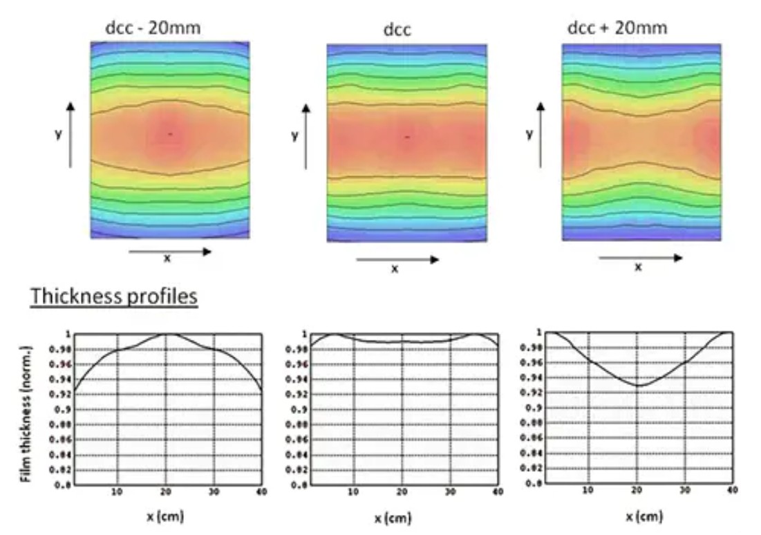
This profile is integrated along the band direction and results in a line profile across the band. The change of the thickness profile and the flux distribution for reduced and for increased cell to cell distance is illustrated in the left and in the right part, respectively. A precise and carefully adjusted arrangement of the deposition setup is necessary to achieve extraordinary film thickness uniformity.
A too small cell to cell distance results in a pronounced maximum thickness in the center of the band. A very large cell to cell distance results in a minimum in the center of the band.
Our proprietary deposition simulation tool provides
- film thickness variations and composition
- material efficiency
- deposition chamber design optimization
- optimization of beam shaping elements
We offer the deposition simulation for your MBE or PVD system as a service. For a specific simulation geometrical boundary conditions of the deposition setup are required.
